News
USB Bridge ICs
Embedded systems that need to be connected to a host computer platform require a universal communication standard. The Universal Serial Bus (USB) is a popular interface standard for enabling communication between an embedded system and a computing platform. Rapid USB adoption in embedded design has pushed developers to include quicker and more economical methods for USB connectivity.
Introduction
Prior to 1996, designers tried to develop convenient microcontroller (MCU) communication peripherals that would complement the desired protocols and communication speed for particular communication tasks. The high-speed transfer of large amounts of embedded data requires a UART or SPI. For example, since RX and TX signals are generated by the MCU, an interface is required to function with terminal software. In contrast, a level translator was used in older devices to connect to the device running the terminal emulation software (through a DB-9 serial cable) and provide RS232-level signals. With RS232 break-out boxes, null modem cables, and the occasional soldering of jumpers between RTS & CTS and DSR & DTR pins, a reliable connection was never a guarantee.
All of these have paved the way for USB. Numerous manufacturers produce USB to UART interface chips that effortlessly change any logic-level serial signal to its USB equivalent. The USB Communications Device Class (CDC) is the most popular, and crops up as a virtual COM port on its host. Some manufacturers use USB Vendor Class in order to specify [or optimize] the data transfer protocol for their devices [intended applications] and so provide drivers for their devices which create a Virtual COM Port as well as access via DLL functions. To use this COM port, the terminal emulator must be configured with the proper communication specifications. Contemporary USB technologies offer high data transfer rates that facilitate simultaneous delivery of power, audio/video, and data for the device and host platform.
The Benefits of USB Bridge ICs
An embedded designer has a variety of MCUs with a built-in USB peripheral interface from which to choose. However, it must be noted that MCUs equipped with an integrated USB feature may lack the memory size, peripherals, and GPIO needed for a particular embedded design specification.
The benefits of using Bridge ICs include the following:
- The entire USB protocol is managed on the chip. There is no requirement of USB-specific firmware programming.
- The connection to a DCP (Dedicated Charging Port) USB port can be detected.
- There are reduced needs for microcontroller resources. Any communication via SPI, UART, or I2C demands less resources compared to USB CDC device class implementation.
- There are free drivers for Windows, Android, Mac OS-X, and Linux.
- The USB/serial bridge connects microcontroller pins to the USB connector, implying that overvoltage or ESD spikes on the USB bus may damage the bridge in-lieu of the microcontroller. The small bridge chip is less expensive and simpler to replace than the microcontroller.
UART-USB Bridge ICs
Figure 1 is a block diagram of the FT232 UART-USB Bridge IC, a powerful chip with a complete USB protocol stuffed within it. No external hardware or firmware is required. The buried microcontroller packed within this chip can perform simple Input/Output operations.
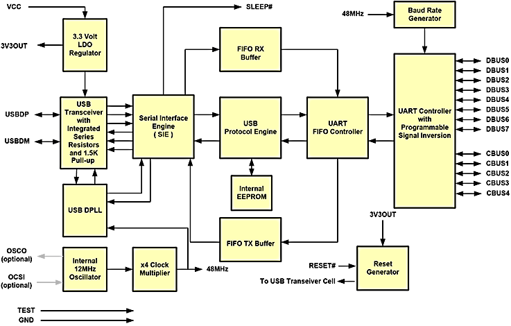
Figure 1: Block Diagram of the FT232 UART-USB Bridge IC (Image Source: FTDI Chip)
- Serial Interface Engine (SIE): The SIE block manages the bulk of the USB communication protocol and works at the front of the USB connector. SIE standard functions include signal detection, Packet ID
generation, clock/data separation, and serial-parallel conversion. - USB Protocol Engine: This helps to develop USB-based devices and their production, and constitutes the USB 2.0 communication core. This protocol engine executes CRC checks, sends and receives data
packets, performs handshake evaluation and response, and address recognition. - FIFO Tx-Rx Buffer & UART FIFO Controller: The receiving and transmitting buffers are 128 and 256 bytes, respectively, for high data rate transmission. The FIFO controller administers the flow of data
from the USB device to the UART, and vice versa. - UART Controller: This controller block converts the data format to send it over the RX and TX UART data lines. This controller is programmable via the FT232’s USB interface to make the DBUS (TXD, RDX,
RTS, CTS, DTR, DSR, DCD, RI) and CBUS pins work as typical GPIO pins. These pins, by factory default,
will work as USB-to-UART communication control pins.
Multichannel USB Bridge ICs
Some complex systems employ their serial or parallel ports to communicate between master and slave controllers. Parallel communication requires a substantial multi-bit address bus and data bus, and this is ideally
limited to short-distance transmission. In contrast, serial communication finds extensive use due to its long transmission distance and simple structure.
Occasionally, however, a common serial port will be unable to satisfy the needs of complex systems with various (and even specialty) baud rate equipment. In such cases, the solution is to choose multiple bridge ICs,
or a single multichannel Bridge IC.
The benefit of a multichannel bridge is that the system BOM is reduced, by taking away the need for a USB hub chip. Additionally, each channel of the device appears to the host PC as a separate device, enabling each channel to be independently configured for different modes, e.g. UART, MPSSE, or FIFO, and with different parameters such as 4 UARTS all operating with different baud rates.
Using Multichannel Bridge ICs
The multichannel controller contains different blocks such as UART, baud rate generator, status detectors, and asynchronous FIFOs. This controller is utilized to implement communications among MCUs within a complex system, and also to enable full communication among high-speed and low-speed devices. It is also possible to design FIFOs and other small-scale memorizers.
A single UART communicates with the PC or the main MCU. The sub-MCUs communicate with other UARTs. Each channel contains two FIFOs, one to transmit data and another to receive it. All sub-MCUs can simultaneously receive data with zero time-lapse among them. Sub-controller synchronization improves when this controller is used.
The benefits of using multichannel USB Bridge ICs include:
- The Multichannel UART offers a high bandwidth solution for high data rate serial transmission protocol communication systems.
- A multi-channel UART has better hardware efficiency compared to individually implemented UARTs.
- Component reuse among several channels can lead to hardware reduction.
Managing Power Requirements
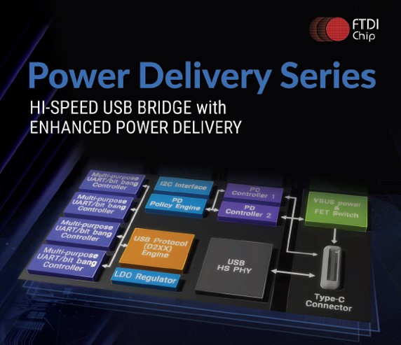
FTDI Chip’s latest multichannel USB interface IC series are capable of managing next-generation power requirements, providing enhanced functionality as larger hardware items begin to adopt the protocol. Such multichannel bridge ICs fully support the latest USB Type-C and Power Delivery (PD) standards, enabling support for power negotiation with the ability to sink or source current to a USB host device. Furthermore, they are in full compliance with the Rev 3.0 USB power delivery (PD) specification.
The Power Delivery series has two Type-C/PD ports, with a PD1 port supporting both power sink and source roles (Initial Sink), and the PD2 port working as a power sink port. Both PD ports support 5V, 9V, 12V, 15V, and 20V PDO profiles, and these profiles are configurable through the external EEPROM at power-up or reset. The PD1 port shares the same Type-C connector with USB data, and the PD2 port is a power port only, without USB data.
In addition to the higher data rates these devices offer (up to 40Mbytes/s) compared to full-speed solutions, the Hi-speed series also offers a range of multichannel interfacing. USB-C is the latest high-speed data transfer standard for audio and video for a few simple reasons. The technology is simultaneously robust and inexpensive, especially when the number of connections is factored in. The USB Type-C connector incorporates a 24-pin connector. PD instructions are issued via Policy Engine (PE) or DPM (DisplayPort (M)) to the power supply. The desired power level and modes are requested while the performance is monitored. The PD chip built into the USB-C connector facilitates communication between the sink and the source, in order to elevate the Vbus supply voltage from a low 5V up to 20V, and current to a maximum of 5A. The USB Type-C PD bolsters dynamic power negotiation, facilitating minimal charge time, maximizing performance and battery life. Other than power output level regulation, the PD chip is characterized by a single wire communication protocol which allows any source to be the power sink and reciprocate both ways.
| FT2233HP/FT2232HP | FT4233HP / FT4232HP | FT233HP/FT232HP |

The FT2233HP/FT2232HP is a Hi-Speed USB device with a Type-C/PD 3.0 controller IC that fully supports the latest USB Type-C and Power Delivery (PD) standards, enabling support for power negotiation with the ability to sink or source current to a USB host device. The USB bridge function delivers two independent channels compatible with the FT2232H. Supports 5V3A, 9V3A, 12V3A, 15V3A, and 20V3A PDOs as sink or source Type-C/PD Physical Layer Protocol, Two Multi-Protocol Synchronous Serial Engine (MPSSE) on channel A and channel B, to simplify synchronous serial protocol (USB to JTAG, I2C, SPI or bit-bang) design, Single-chip USB to two channels UART (RS232, RS422 or RS485) or FIFO modes, Single-chip USB to one SPI channel and one UART. |
The FT4233HP/FT4232HP is a Hi-Speed USB device with a Type-C/PD 3.0 controller IC that fully supports the latest USB Type-C and Power Delivery (PD) standards, enabling support for power negotiation with the ability to sink or source current to a USB host device. The USB bridge function delivers four independent channels compatible with the FT4232H. Supports 5V3A, 9V3A, 12V3A, 15V3A, and 20V3A PDOs as sink or source Type-C/PD Physical Layer Protocol, Two Multi-Protocol Synchronous Serial Engine (MPSSE) on channel A and channel B, to simplify synchronous serial protocol (USB to JTAG, I2C, SPI or bit-bang) design, Single-chip USB to four channels UART (RS232, RS422 or RS485).The FT4233HP/FT4232HP can be used as a single chip USB to 2 I2C channels plus 2 UARTS, 2 JTAG channels plus 2 UARTS, 2 SPI channels plus 2 UARTS or 1 SPI channel, plus 1 JTAG channel plus 2 UARTS. |

The FT233HP/FT232HP is a Hi-Speed USB device with Type-C/PD 3.0 controller IC that fully supports the latest USB Type-C and Power Delivery (PD) standards enabling support for power negotiation with the ability to sink or source current to a USB host device. The USB bridge function delivers one independent channel compatible with the FT232H. Supports 5V3A, 9V3A, 12V3A, 15V3A, and 20V3A PDOs as sink or source Type-C/PD Physical Layer Protocol, One Multi-Protocol Synchronous Serial Engine (MPSSE) to simplify synchronous serial protocol (USB to JTAG, I2C, SPI or bit-bang) design, Single-chip USB to UART (RS232, RS422 or RS485) or FIFO modes. |
Taggings: